I use CCS from www.ccsinfo.com and C18 MPLAB from www.microchip.com as the compiler. Comparing to each, CCS is very easy to use as it has many function in lib, however this software is licensed. For C18, you need to make the lib or some routine with yourself but it is free software for all. up to you for use.
Please see on mp3 page to view the first project made based on PIC, and this is the second project, education board for experiment usage.
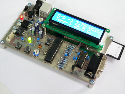
Hardware
- PIC16F876
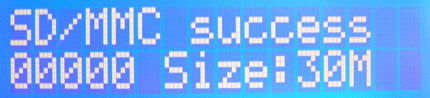
- One socket for SD/MMC SPI interface
- 4 Bit LCD HD44780 interface
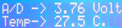
- 1 wire DS1820S for temperature sensor -55 to +125C
- 2 Bottom switch, 1 LED, 1 A/D port
- RS232 Serial Port
- Expand 2 bit for external I/O
- In circuit programming RJ-11 Connector Standard http://www.inex.co.th/micro/programmer.html programming tools device
- Power supply + 12 Volt
Software You can easily learn the basic of PIC with this education board. The hardware on board prepared to adapt to many devices. The compiler used is CCS Compiler version 3.249. Now my source code is available in C language.
 |  |  |
Pic USB Application PIC18F4550
This article is an introduction to designing a USB PIC based device. It is based on the original C# API I developed, and heavily influenced with my friend J1M www.hobbypic.com ,For this pic project he is the very helpful person and advise me a lot to complete this version. The article will demonstrate how to use a PIC18F4550 to produce a USB full speed 2.0 Device which will perform basic input/output operations, whilst communicating with a C#.Net application via the microchip drivers.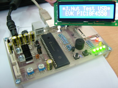
Overview
It is important to consider how the overall system is going to work, and how the different components interact with each other to complete the overall task which in this case is a rather trivial one. At the basic level we are going to use the on board USB interface on the PIC to communicate with PC. Once the pic is connected to the PC, We shall be using the standard microchip drivers to communicate with the device. This forms a data channel from Windows to a segment of code in the PIC. The final link in the chain is the code at both ends of the channel, which can be customized to produce the functionality required.
Hardware
The basic hardware design can be seen picture. It are demo board from me, then that’s perfect for basic USB..The only slight complication with the hardware is that I was using a USB On The Go (OTG) connector, and if you don’t want to use one of these you'll find a normal USB connector only has 4 pins available, The hardware on Board 2 A/D port, 2 Bottom switch, 4 leds, 1 buzzer, 16 char 2 line LCD, SPI for SD/MMC, in circuit programming.
PIC Software
The example PIC complete code in this article can be found page download. Extract the zip file into C language. To compile the PIC Source code with CCS version 3.249 All being well the code should have compiled successfully, however if it is unsuccessful please go back and check all the project and include paths are setup correctly. (Any other strange errors please let me know)
You should now be able to test the code, to do this program the hardware using your favor ate PIC programmer, and connect it to your test PC (warning check the hardware first, there is a risk of causing damage to the PC), all being well the PC should request for the drivers for a "PIC18F4550 Family Device", you can now either skip to the Driver section or keep reading if you want to understand how to add in extra functionality to the device.
Windows Drivers
Now you've built the hardware, compiled the source, you are ready to go. All being well when you connect the PIC to the PC, windows should request the drivers, if not go back and check the hardware and that the PIC programmed correctly. 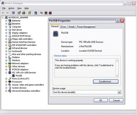 The drivers we shall be using are the standard Microchip ones, and modified some one. These changed to alter the icon, change the device class etc... However this isn’t the place to explain all that, all being well a new article might come out containing this information. The drivers can be found below, or in the complete code at the start of the article. Hopefully you shouldn't have any issues installing these (as long as windows ask's for them, you should be in the clear), so I'll assume you are all technically competent enough to do this (as you are designing USB stuff after all!!).Once the drivers are installed correctly, after connected to the pic ready led should be on alternatively to indicate the connection has been established.
Application Code
The application code can be found download page. The application was developed using C# Express 2005; In order to run the code (or compile it for that matter) you will also require the .NET Frame work to be installed. The code should be pretty self explanatory however I will go over the general concepts.
Example Application 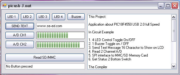
The idea program is to create a simple way of controlling 4 LED's, A/D, LCD, SPI for SD/MMC and many attached on Board, The application consists of three main parts, the mpusbapi.dll, USB interface class and the main form. The DLL (located in the debug directory) acts an interface between the application and windows driver, therefore do not modify this, and just ensure that it is located in the directory of the program. If you need some more, Can be study and modify base my code.
Again, it is no warranty on that and it is not encouraged use it for commercial purpose. You may distribute it or modify it. If you see any bugs with my code or have better idea to improve, please feed back to me as I am always looking for positive suggestion. I belive, you can make progress with your self....


No comments:
Post a Comment